FOREWORD
The following project has been done as a part of my M.Tech research work (Human Detection and Tracking with SLAM through a Mobile Armed Robot) in collaboration with Sandeep Kumar Palo (M.Tech in Industrial Power and Automation, National Institute of Technology Calicut) under the guidance of Mr. A.P. Sudheer (Mechatronics/Robotics Lab In-charge, National Institute of Technology Calicut). For any queries regarding SLAM Robot you may contact Sandeep at skpthe1@gmail.com or me at hashim_kahily@live.in.
If I say SLAM, what comes to your mind first? If Basketball is the answer then you should probably get yourself updated to the technological advancement happening around you.
SLAM is one of the most widely researched sub-fields of robotics. The term SLAM is as stated an acronym for Simultaneous Localization And Mapping. SLAM is concerned with the problem of building a map of an unknown environment by a mobile robot while at the same time navigating the environment using the map. I’d advise you to visit this link in order to understand general concepts of SLAM on an introductory level. For research purpose, a holy grail of information regarding SLAM can be found at OpenSLAM.org. In addition to that, video lectures by the professors from the University of Freiburg should familiarize you with the basic concepts and techniques used within the field of mobile robotics.
SLAM has a large number of applications, some of the real life applications include:
- search/rescue operations in contaminated areas
- reconnaissance missions for military activities
- underwater reef monitoring
- exploration of mines
- outer space explorations
You would probably want to ask me that why make a website when there are already a number of resources available for SLAM. Well, my answer to that is, all the websites and videos regarding SLAM either describes the theoretical concepts behind SLAM or demonstrates standard robots performing SLAM. You may never seem to find anything like “A precise practical approach towards SLAM using your own robot”. However, ROS Navigation Tutorials does lend a helping hand into that problem but you may still encounter a lot of confusion and uncertainty should you attempt to follow those tutorials. So I decided that if I successfully implemented SLAM, I’d write a detailed account of the steps in the hopes that it might be helpful to SLAM enthusiasts. I’m pleased to say that I did get it, and so here is my account.
The following video demonstrates my mobile robot performing real-time SLAM using a Kinect sensor. A 2-D occupancy grid map (like a building floor-plan) is created from laser and pose data collected by the mobile robot.
I’d no longer fan the burning flames of your curiosity and move straight forward to the “How to make your own SLAM robot” part.
Explanations
I) Prerequisites and Software Installation Guide
II) The physical robot
III) Setting up your robot in ROS
IV) Motion and Sensor Models
V) SLAM Execution
VI) Further Reading
I) Prerequisites and Software Installation Guide:
In order to perform SLAM using your personal robot you are required to have:
- A computer (preferably a laptop) with a Linux distribution. Although any Linux distribution should be fine, it is recommended that you use a LTS version of Ubuntu (I used 12.04).
- A basic understanding of Robot Operating System (ROS).
- ROS Hydro installed in your system.
- A Microsoft Kinect Sensor and its ROS drivers.
- An exposure to Arduino microcontroller platform and its packages installed in ROS.
- A basic knowledge of Linux tools and some C++ programming skills.
- A mobile robot (detailed explanation has been provided in the next section).
1. Ubuntu is one of the most popular forms of the Linux operating system. It is available for free, and will run on almost any computer. There are two ways to install Ubuntu in your system- alongside windows and inside windows. This guide contains a comprehensive information regarding Ubuntu installation in your system as per your preference.
2. ROS is the Robot Operating System framework, which is used nowadays by hundreds of research groups and companies in the robotics industry. With ROS, you will start to program and control your robots the easy way using tons of examples and source code that will show you how to use sensors and devices or add new functionalities to your robot, such as autonomous navigation and visual perception. Thanks to the open source motto and the community that is developing the state-of-the-art algorithms and providing new functionalities, ROS is growing every day. The potential of ROS is illustrated with the ability to work with whole robots in a simulated environment.
I’d suggest you to go through this book before proceeding further. The goal of this book is to provide an integrated overview of the concepts and techniques you’ll need to know to write ROS software. It presents a selected subset of ROS features that, in the author’s view, represents a useful starting point for using ROS. Anyone who is learning robotics and has heard about ROS but has never tried it will benefit from this book. After all, learning to use a new framework, particularly one as complex and diverse as ROS, can take quite a lot of time and mental energy, so one should be certain that the investment will be worthwhile.
3. The installation process has been explained in detail in the official ROS page: http://wiki.ros.org/hydro/Installation/Ubuntu
4. The Kinect was launched on November 4, 2010 and sold an impressive 8 million units in the first 60 days, entering the Guinness World Records as the “fastest selling consumer electronics device in history.” It enables users to control the game with physical gestures and voice-based command. It has not just used in the gaming system but has been implemented in various applications like unmanned aerial vehicle (UAV), human recognition, 3D model re- construction, ground mobile robot navigation and medical applications. Kinect is used to perform SLAM, instead of a laser scanner in this project.
To run the Kinect sensor in ROS you’ll need to install two drivers in your ROS system. Fire up your Ubuntu command terminal and paste this line for installation.
sudo apt-get install ros-hydro-openni-camera ros-hydro-openni-launch
This tutorial demonstrates how to open a Kinect (or other OpenNI device) in ROS, introduces ROS tools for visualization and configuration, and explains how to get registered (depth + RGB) outputs like color point clouds.
5. Arduino is an open source electronics prototyping platform composed of a microcontroller, a programming language, and an IDE. Arduino can be used to develop interactive objects, taking inputs from a variety of switches or sensors, and controlling a variety of lights, motors, and other physical outputs. The open-source IDE for your Ubuntu can be downloaded for free from http://playground.arduino.cc/Linux/Ubuntu.
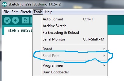
After the installation of arduino IDE in Ubuntu, the serial port will not be detected when the Arduino board is plugged in via usb. It is all a matter of permission, typical Linux! The issue with the permissions for /dev/ttyACM0 can be permanently solved by typing the following line in your terminal.
sudo chmod a+rw /dev/ttyACM0
Your Arduino board should be properly configured now, the Arduino IDE should be installed on your computer, and you should be communicating seamlessly with your board via USB. If this is your first contact with Arduino, you might want to consider having a look at this book before you go deeper into the project.
Moreover for this project, Arduino packages needs to be installed in ROS for serial communication. This tutorial shows step-by-step how to setup up and use ROS directly with the Arduino IDE.
6. Cprogramming.com is a totally free website devoted to teaching you to program in C++. Whether you’ve had any prior experience programming or not, the tutorials on this site will walk you through all the steps you’ll need to know in order to create and compile your programs. Also, peruse through this How to Get Familiar With Ubuntu Commands guide to get a basic understanding of Ubuntu commands.
II) The Physical Robot:
To implement SLAM you need to have a mobile robot and a range measurement device (Kinect in our case). The mobile robots we consider are wheeled indoor robots. The focus of this document is mainly on simple differential-drive mobile base and does not explore robots with complicated motion models (models of how the robot moves) such as humanoid robots, autonomous underwater vehicles, autonomous planes, robots with weird wheel configurations etc.
Obtaining odometry data of your robot is one of the two cornerstone of performing SLAM. Odometry is the use of data from motion sensors to estimate change in position over time. Odometry is used to estimate (not determine) their position relative to a starting location.
To obtain the odometry data you need to have:
- A mobile base.
- DC motors to drive the wheels.
- Encoders to estimate the position and orientation of the robot.
- Some means to control the motors.
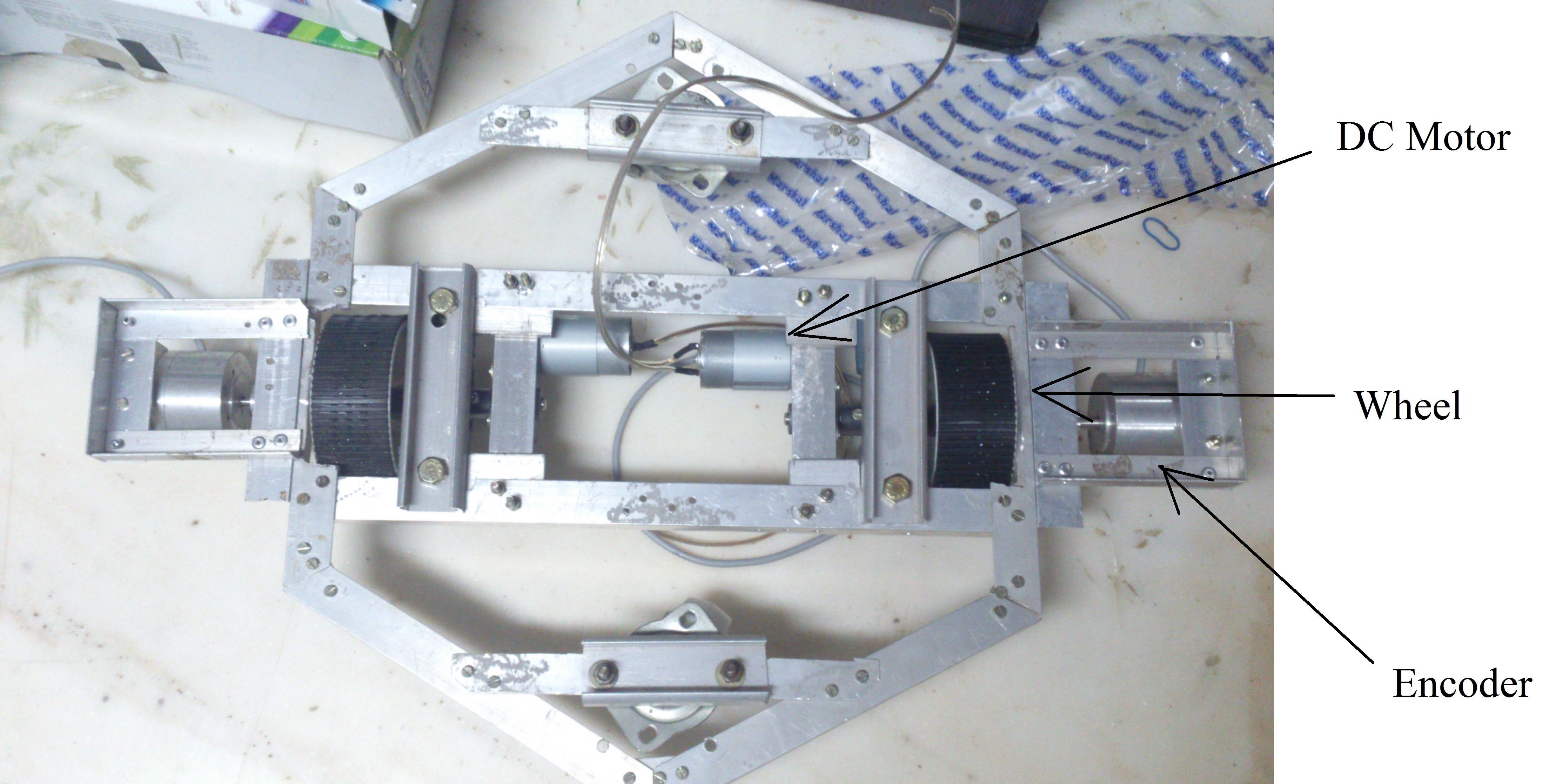
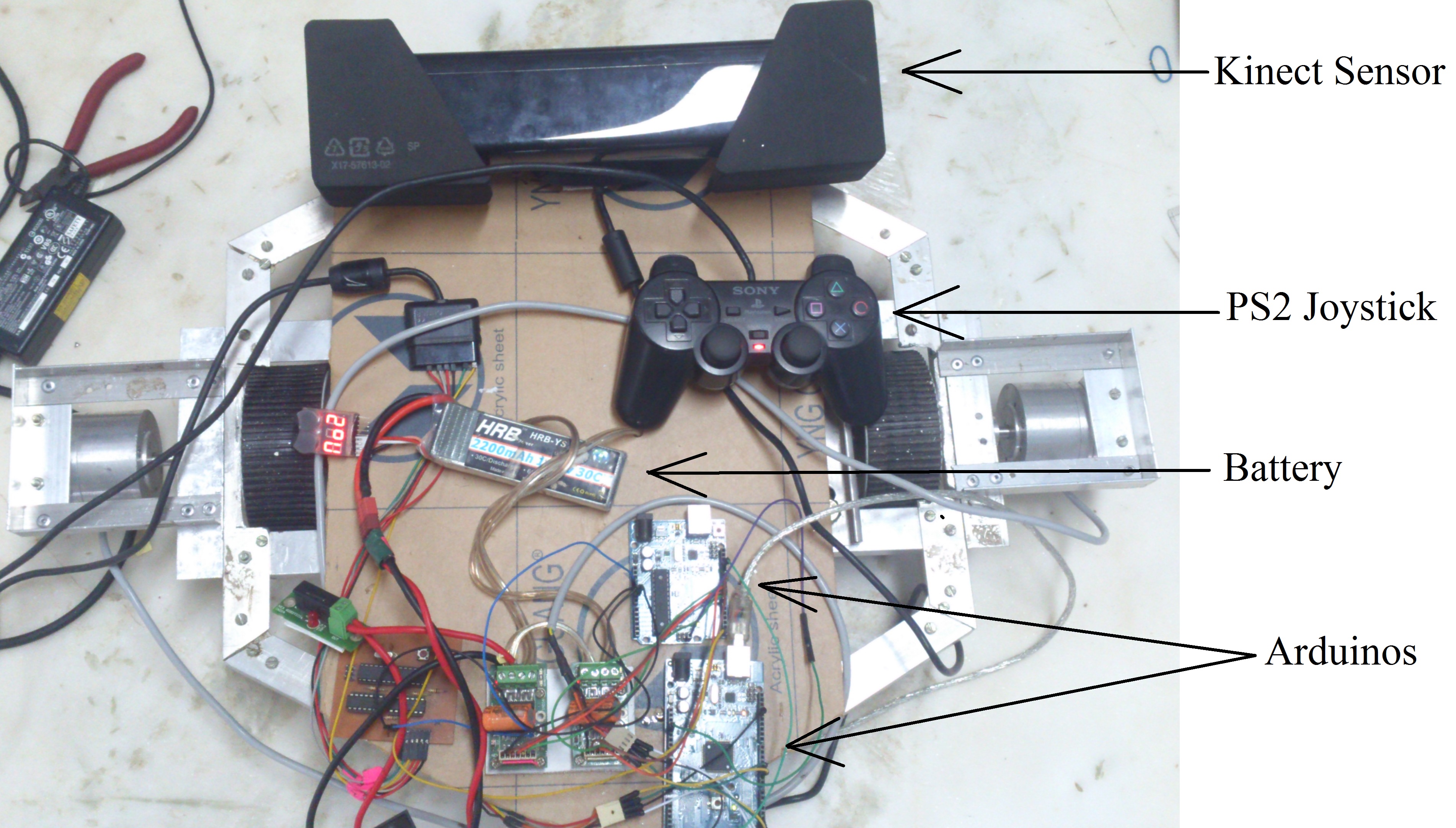
The following pictures shows the mobile base of my robot.
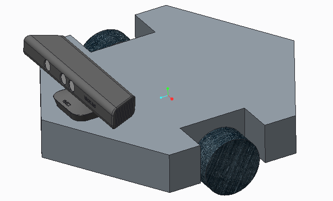
The CAD Model
You need to check the mass of your robot before selecting the DC motors to drive the robot. This link might help you determine the torque required at each wheel to drive the robot.
In order to read signals from the encoders when your robot moves, you are required to install an encoder library in your Arduino environment. This website provides you with the necessary library alongwith basic explanation about encoders.
I’ve used a PS2 joystick to control the DC motors. If you too have a PS2 joystick and intend to use it to drive your robot, you can visit this site which addresses the communication between Arduino and PS2 joysticks.
The following Arduino code is used to give motion commands to my robot using the PS2 joystick.
arduino_PS2.ino Visit https://github.com/hashimK/Slam-Robot to obtain the code.
III) Setting up your robot in ROS
To generate maps in the ROS simulation world, you are required to have a 3D model of your robot setup in ROS. To create geometrically accurate model of the robot and describe the configuration of links and joints of the robot, ROS uses an XML file written in the Unified Robot Description Format (URDF). There is large set of tutorials on how to build up your own robot models using the URDF specification. Check out this urdf/Tutorials page to represent your robot model.
The following image shows the URDF model of my robot in RVIZ (3D visualization tool for ROS). The dimensions of the URDF model along with the sensor frame position is in complete agreement with the physical robot in metres.
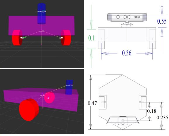
The URDF model in RVIZ
You might find some help in making your URDF file by examining the my URDF file for the above robot. Open up your text editor in Ubuntu and save the following code as robot.urdf.
robot.urdf Visit https://github.com/hashimK/Slam-Robot to obtain the code.
Now that we have the model of our robot, we can use it on rviz to watch it in 3D. We will create a display.launch file in our ROS workstation, and put the following code in it:
display.launch Visit https://github.com/hashimK/Slam-Robot to obtain the code.
We will launch it with the following command:
$ roslaunch pkg-name display.launch model:='$(find pkg-name)/robot.urdf'
where pkg-name is the name of the package that the file is in (single quotes required).
If everything is fine, you will see the RVIZ window pop up. Choose odom as your fixed frame (under Global Options). Then choose “Add Display” and add a Robot Model Display and a TF Display to examine your model.
IV) Motion and Sensor Model
Motion and Sensor models are the two essential cornerstones for SLAM execution. These two models are required as an input by the SLAM algorithm. The motion model contains the odometry information of the robot and the sensor model consist of converting the Kinect’s depth image into laser scans.
The motion model provides the pose information of the robot for SLAM implementation. The temporal position data of the robot is obtained by following the forward kinematic equations for differential drive robots. The velocity and position
data of the robot is obtained from the arduino board with the help of incremental encoders as mentioned earlier.
Following is the Arduino code that reads the encoder signals and sends the information to ROS.
arduino_encoder.ino Visit https://github.com/hashimK/Slam-Robot to obtain the code.
The odometry is the distance of something relative to a point. In our case, it is the distance between base_link (the coordinate frame rigidly attached to the mobile base) and a world-fixed frame i.e odom. As the odometry is the displacement between two frames, it is necessary to publish the transform of it. The TF package transforms between different coordinate frames used by your robot and keeps track of these transforms over time. A good understanding of TF is essential when working with any real robot. It is worthwhile to work through the tutorials.
The following ROS node is created which subscribes to the Arduino node in order to use the encoder signals for odometry purpose. In addition to that, this node publishes transform from a “odom” coordinate frame to a “base_link” coordinate frame over tf.
odometry.cpp Visit https://github.com/hashimK/Slam-Robot to obtain the code.
The following video shows the movement of the URDF model in Rviz when the physical model of the robot is moved in the real world.
For the sensor model, ROS provides us with a depthimage_to_laserscan node which takes a depth image (obtained by OpenNI devices) and generates a 2D laser scan. The laser scans can be viewed in RVIZ by running the following code in the command terminal.
rosrun depthimage_to_laserscan depthimage_to_laserscan image:=/camera/depth/image_raw
V) SLAM Execution
Finally we are ready to get SLAM working. So far the robot is configured with the sensor and motion model and in the next
step, the gmapping package of ROS is used to generate the map.The gmapping package provides laser-based SLAM, as
a ROS node called slam gmapping. Using slam gmapping,a 2-D occupancy grid map (like a building oor plan) is created from laser and pose data collected by a mobile robot. The slam gmapping node subscribes in tandem to both /scan topic obtained from the sensor model and the tf buffer.
The following launch file does a number things, it:
- opens the OpenNI device (Kinect)
- starts Rviz
- loads our URDF model in RVIZ
- runs the rosserial client application that forwards our Arduino messages to the rest of ROS.
- runs the odometry node that publishes tf transform between base_link and odom frame.
- launches the Kinect based laser scanner as discussed above.
final.launch Visit https://github.com/hashimK/Slam-Robot to obtain the code.
After running the above launch file, we run the gmapping node to generate maps. The following command puts the gmapping node into effect.
rosrun gmapping slam_gmapping scan:=/scan
To view the map getting generated in RVIZ, click on “add a display”, then “map” and set it to the topic /map.
When you start to move the robot with the joystick, you will see the free and the unknown space on the RVIZ screen as well as the map with the occupied space; this is known as an Occupancy Grid Map (OGM). The slam_mapping node updates the map state when the robot moves, or more specifically, when (after some motion) it has a good estimate of the robot’s location and how the map is. It takes the laser scans and the odometry and builds the OGM for you.
The following video shows the SLAM results obtained by our robot. The white areas are considered unoccupied. Grey areas are unknown and black indicates a solid boundary such as a wall.
VI) Further Reading
If you are really interested in this topic, or are researching on a related topic, you may want to do further reading beyond my website. There is lots of information available and there is always more to read if you have the time. A reasonable number of works which you may consult for additional and more detailed coverage of SLAM and ROS are as follows:

Great.. Awesome
its good hashim
Gr8 job buddy
This post and many other on your page are very interesting.
You should show your content to wider audience. There is a big chance to go viral.
You need initial boost and visitors will flood your website in no time.
Simply search in google for:
Juuri13 viral effect
It’ѕ awesome foг mе to have а website, wɦiсh iss helpful fοr mƴ knowledge.
thаnks admin
Well explained! helpful!
Can you tell what is the hardware requirement for this in details,
Hello Saurabh, the SLAM webpage mentions all the necessary hardware requirements in detail
Hi bro !!
first thing i am very much happy to see this post because i am very much interested and working a lot to implement slam on robots what i have built.(quad copter,RC car) etc.
1000 thanks for u r patience of explaining each and every step in detail.
and i would like to ask a question
“can we make this autonomous? like without using the ps2 ground/control”
Yes, it can be automated.
Further reading beyond my website explanation is the answer.